
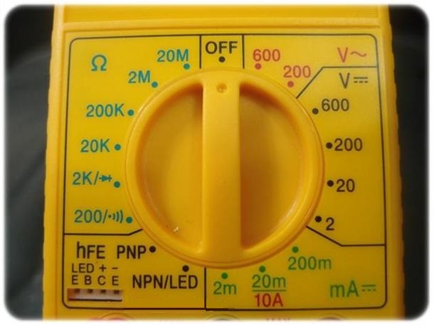
As the figure (figure from internet), the portion of left-upper side is for resistance measurement.The value of each mode indicate the maximal measurable resistance. In case that the multimeter displays OL, it means overloaded, so just try a higher mode for correct measurement.In the mode of 2K (along with a diode symbol), user can use to check the polarity of LED. LED will light up as positive probe connected to anode terminal of LED and negative probe connected to the cathode terminal of LED.
The portion of right-upper side (with the mark V~) is for AC voltage measurement, for example, wall power 110V or 220V.
The portion of right side (with the mark V =) is for DC voltage measurement, for example, battery power or the voltage of power controller (not DCC decoder) of model railroads.The portion of right-bottom side (with the mark mA = ) is for DC current measurement.
The portion of left-bottom side (with the mark hFE) is for bipolar (PNP and NPN) measurement,
External reference link : https://learn.sparkfun.com/tutorials/how-to-use-a-multimeter/all.