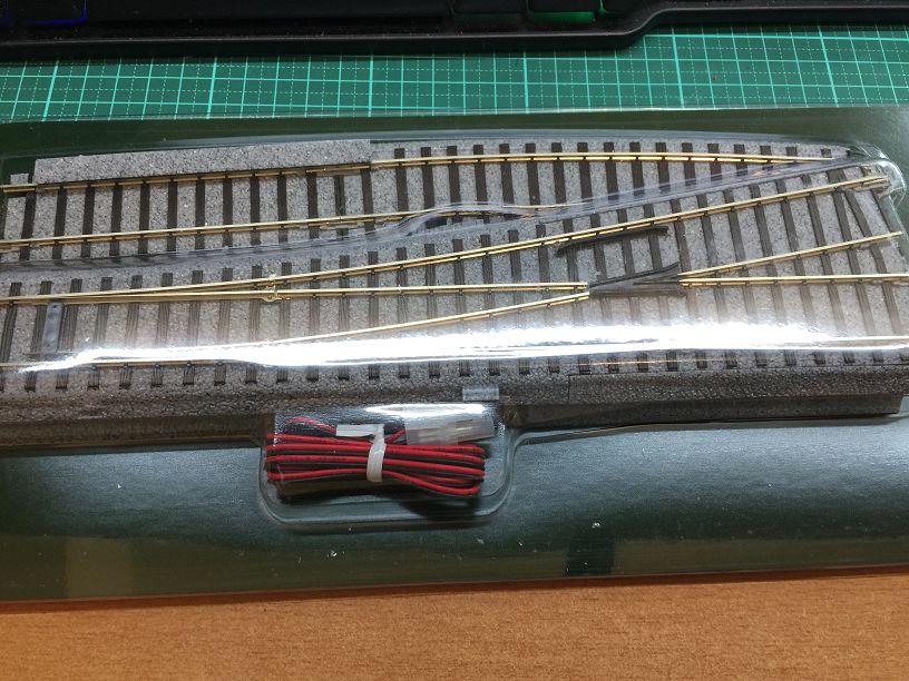
![](http://drm.com.tw/wp-content/uploads/2020/07/IMG_1086001.jpg)
Modified turnout.
![](http://drm.com.tw/wp-content/uploads/2020/07/IMG_1087001.jpg)
![](http://drm.com.tw/wp-content/uploads/2020/07/IMG_1088001.jpg)
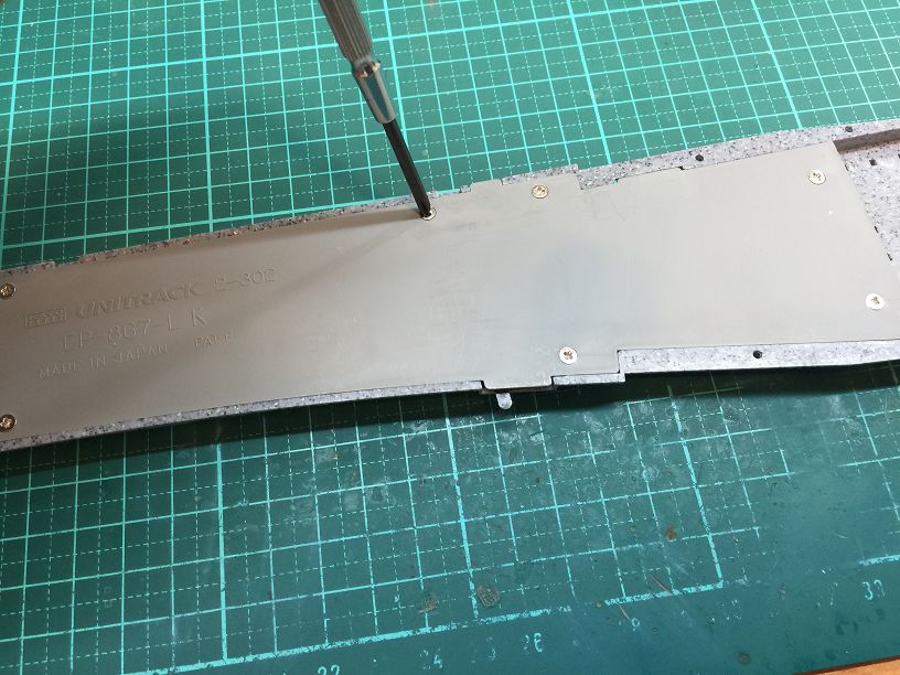
The screw on the back opens.
![](http://drm.com.tw/wp-content/uploads/2020/07/IMG_1089001.jpg)
![](http://drm.com.tw/wp-content/uploads/2020/07/IMG_1090001.jpg)
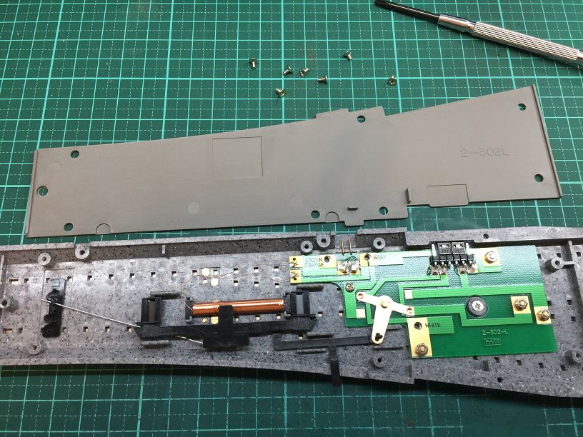
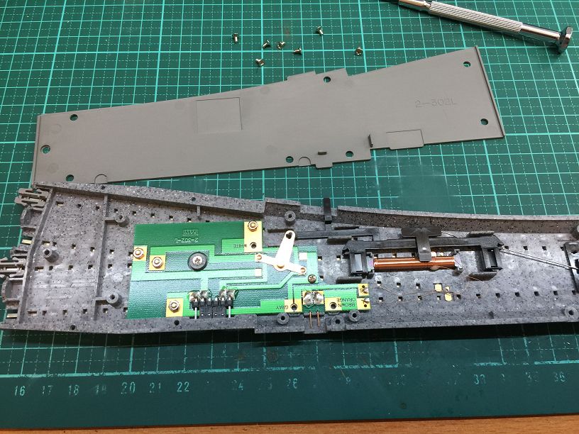
State after disassembly.
![](http://drm.com.tw/wp-content/uploads/2020/07/IMG_1091001.jpg)
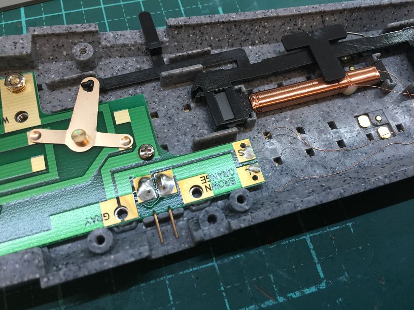
Desoldering the coil.
![](http://drm.com.tw/wp-content/uploads/2020/07/IMG_1092001.jpg)
![](http://drm.com.tw/wp-content/uploads/2020/07/IMG_1093001.jpg)
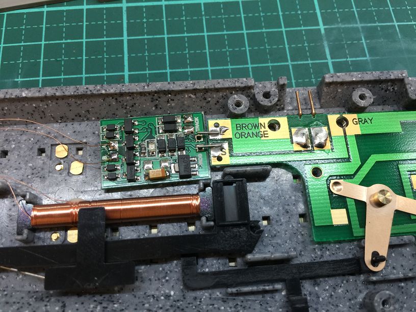
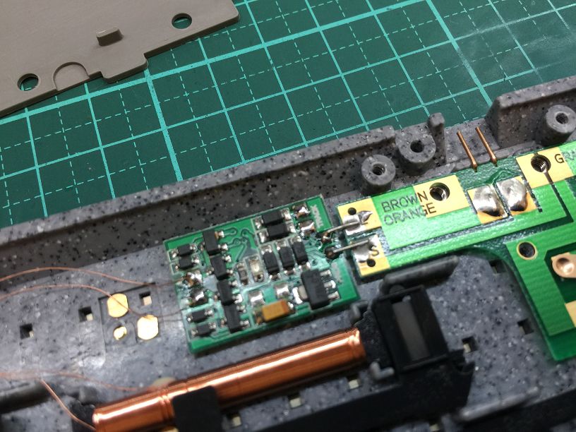
The PROG contact on the decoder is soldered to the PCB coil contact. The original external power terminal is used as the setting contact.
![](http://drm.com.tw/wp-content/uploads/2020/07/IMG_1094001.jpg)
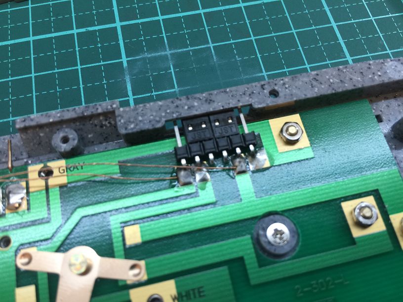
Solder two rail power cords.
![](http://drm.com.tw/wp-content/uploads/2020/07/IMG_1095001.jpg)
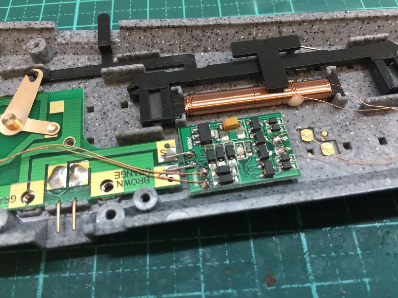
The power cord is connected to the power terminal of the decoder. The coil is connected to the output terminal of the decoder.
![](http://drm.com.tw/wp-content/uploads/2020/07/IMG_1096001.jpg)
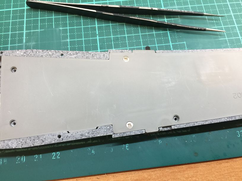
The screw back is completed.