
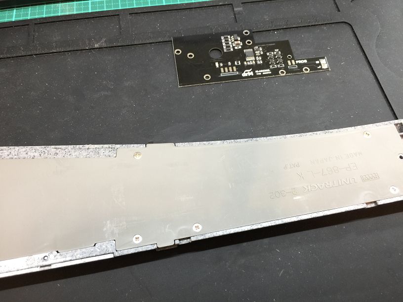
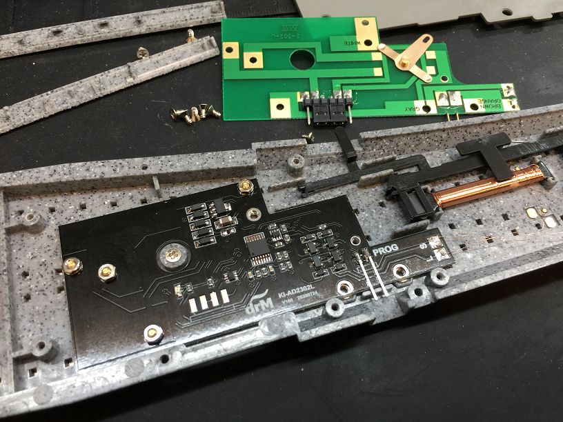
準備軌道與KI-AD2302L解碼器
Prepare the track and KI-AD2302L decoder.
拆下背面7個螺絲
Remove the 7 screws on the back.
打開背板內部狀態.
Open the internal status of the back panel.
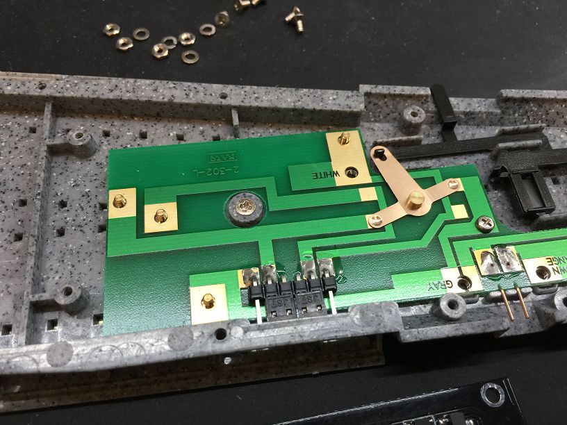
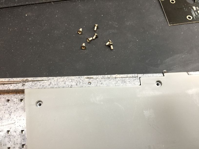
卸下PCB 4個固定螺絲
Remove the 4 fixing screws of the PCB.
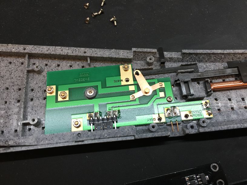
卸下中間PCB螺絲.
Remove the middle PCB screw.
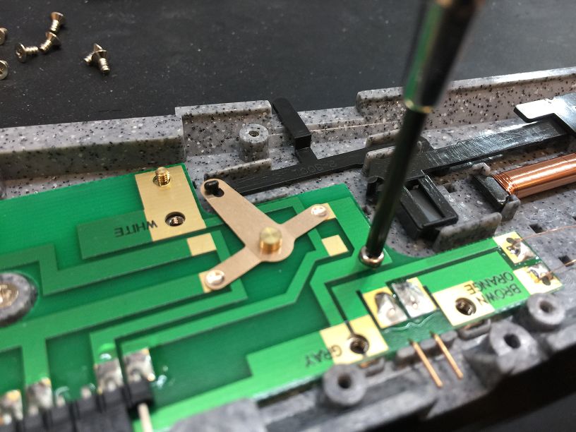
切換銅片與撥桿分開.
The switch copper is separated from the lever.
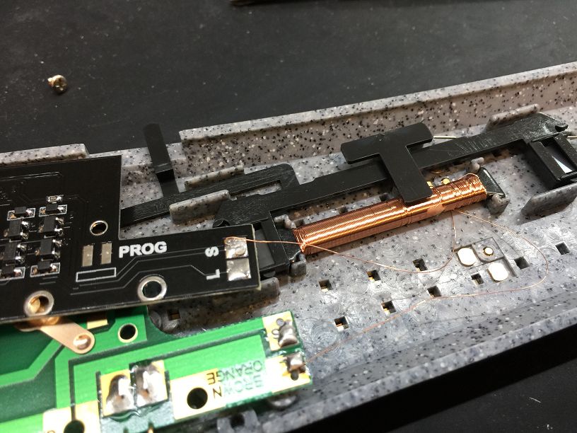
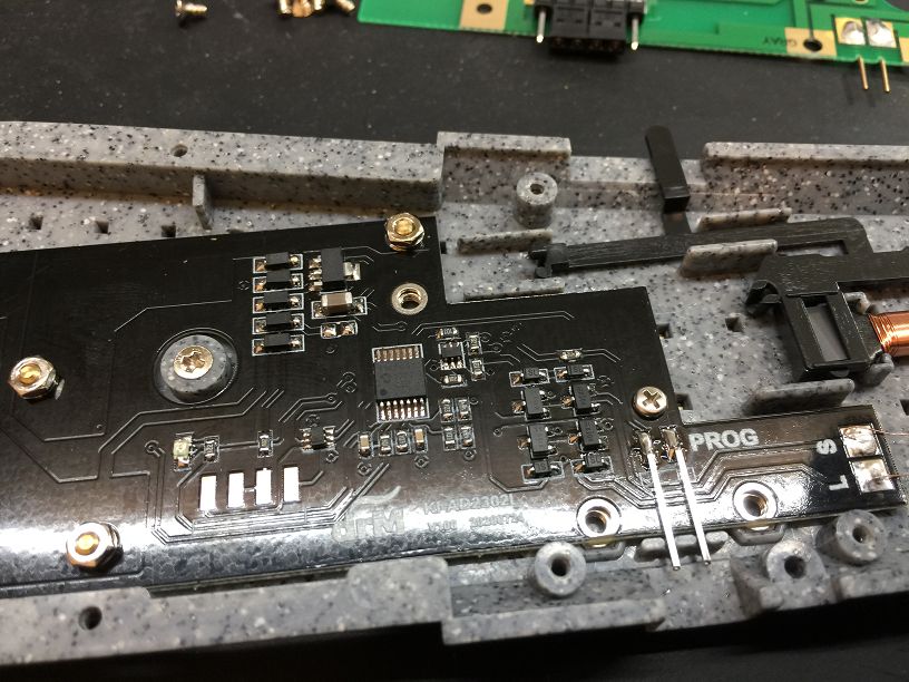
將線圈 S 點解焊後焊接到KI-AD2302L S 焊點.
Desolder the coil S point and solder it to the KI-AD2302L S solder point.
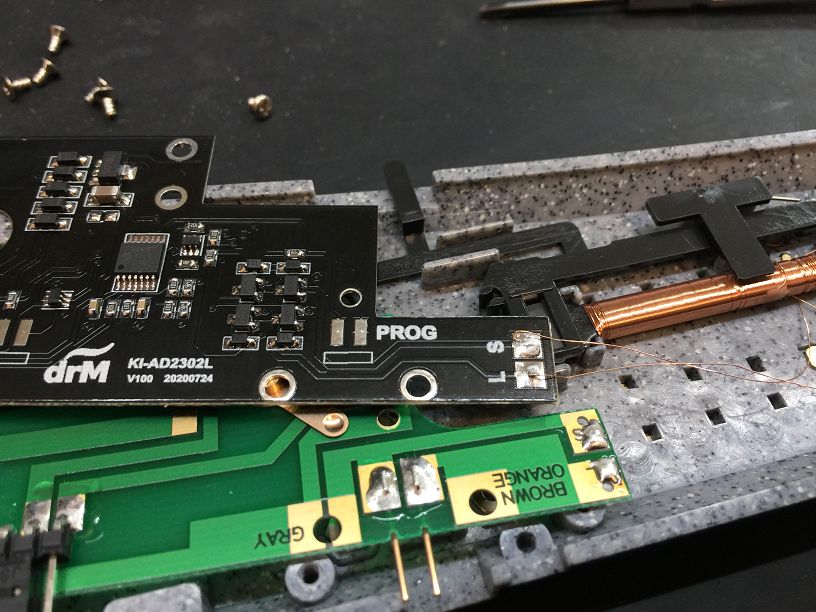
將線圈 L 點解焊後焊接到KI-AD2302L L 焊點.
Desolder the coil L point and solder it to the KI-AD2302L L solder point.
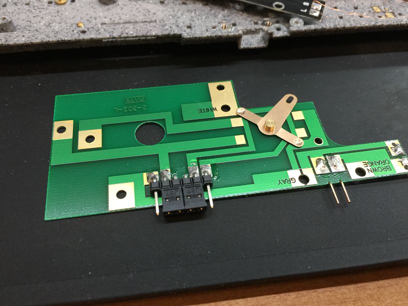
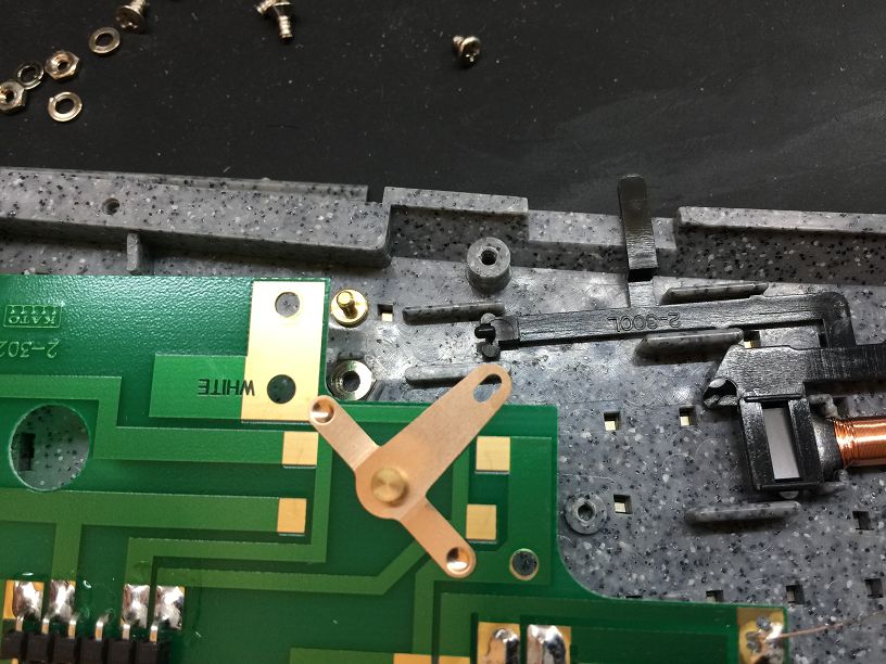
取出原來PCB
Take out the original PCB.
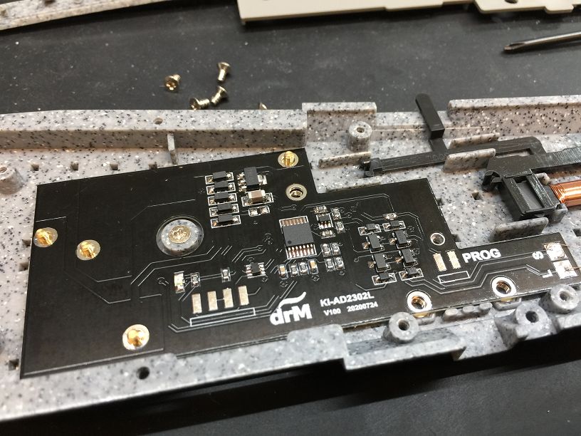
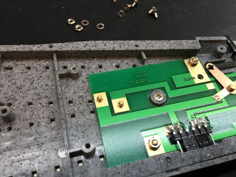
將KI-AD2302L解碼器放入原來PCB位置.
Put the KI-AD2302L decoder into the original PCB position.
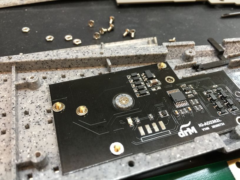
將4個墊片與螺帽裝回螺絲上.
Put the 4 washers and nuts back on the screws.
將中間螺絲鎖回PCB後,蓋回軌道背蓋及螺絲完成安裝.
After locking the middle screw back to the PCB, replace the track back cover and screw to complete the installation.