
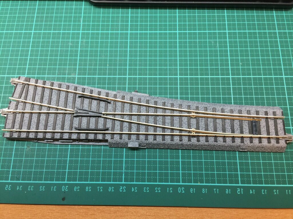
This is the demonstration of installing DCC decoder on Kato HO turnout.
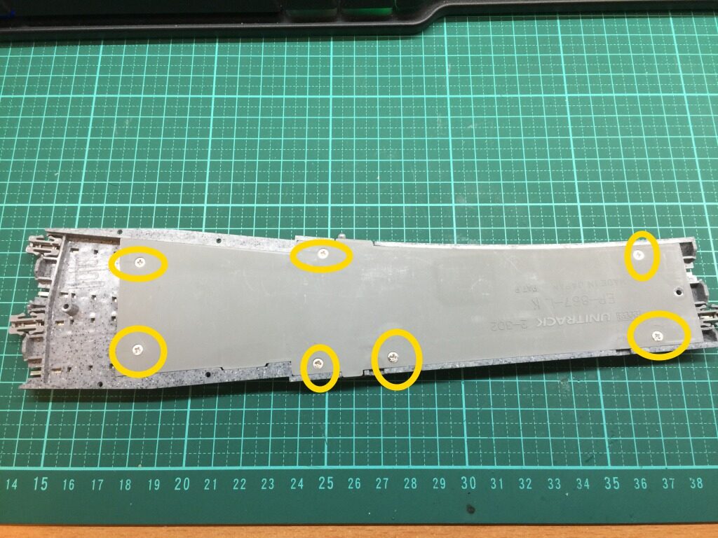
Come off the PCB after undo seven screws which are marked in YELLOW circles.
The default JUMPER setting (which is marked in YELLOW circle) is for analog mode.
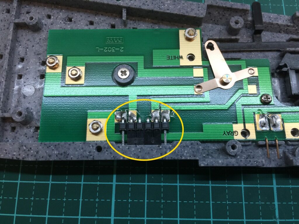
To install DCC decoder, have to modify the JUMPER setting to let all rails are shortened together as the figure.
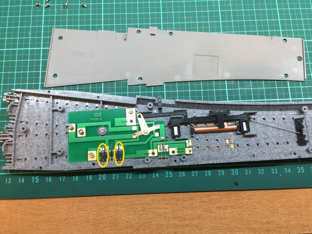
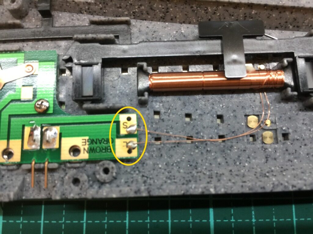
The contacts which is marked in YELLOW circle are the point to connect with DCC decoder.
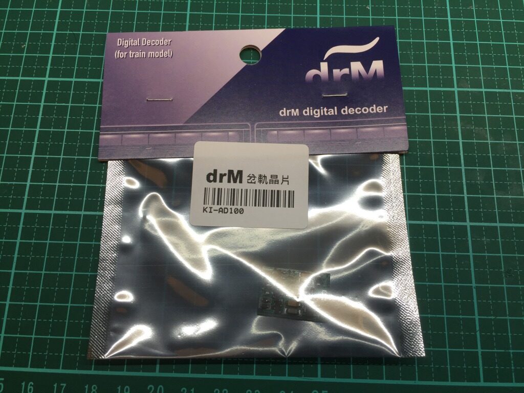
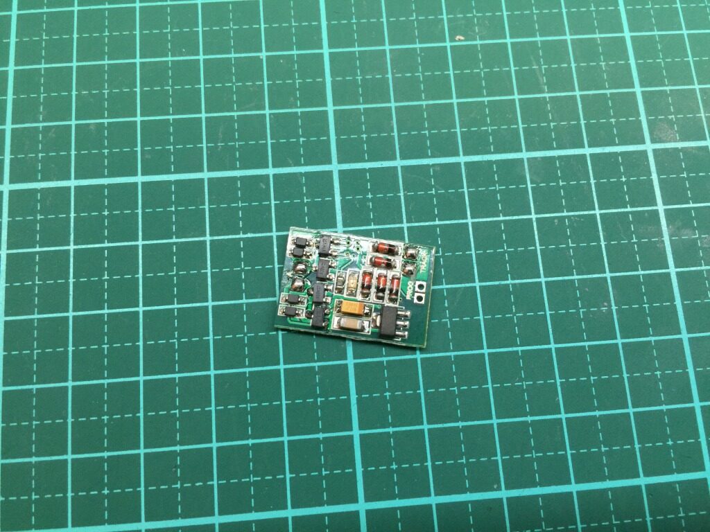
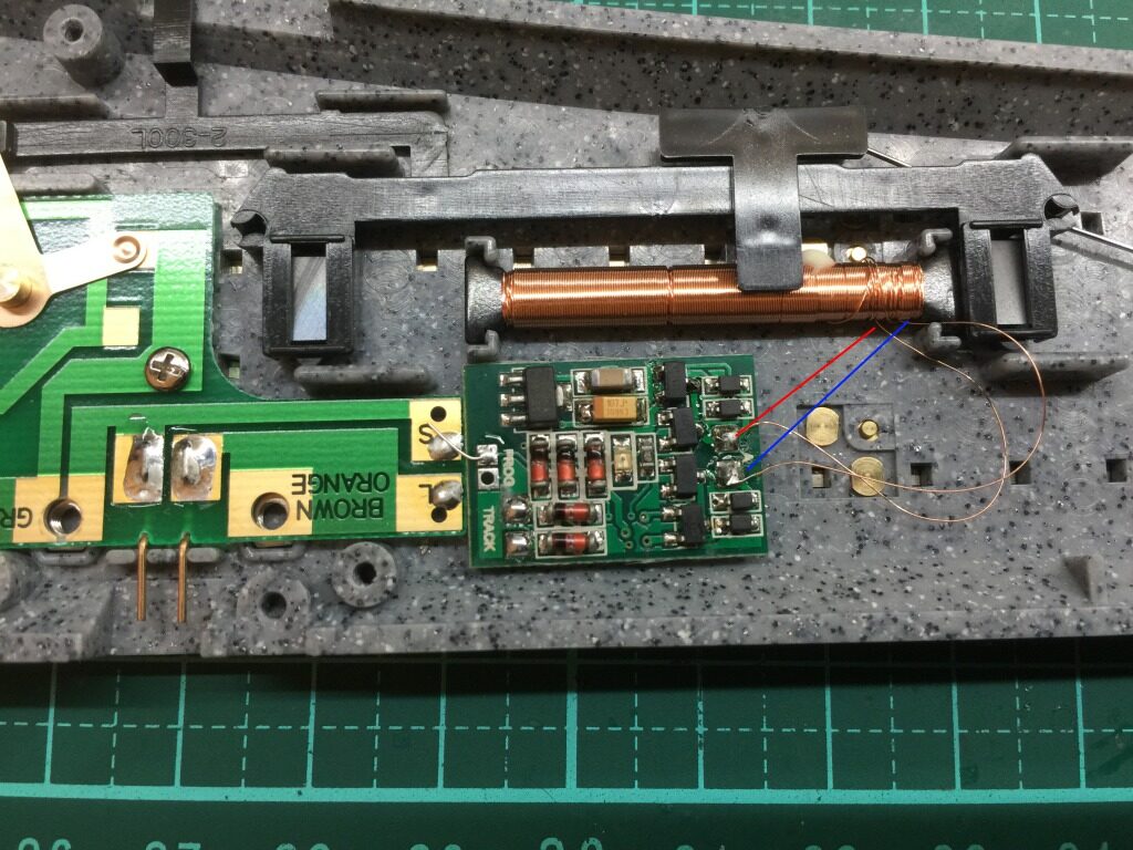
One DCC decoder is prepared.
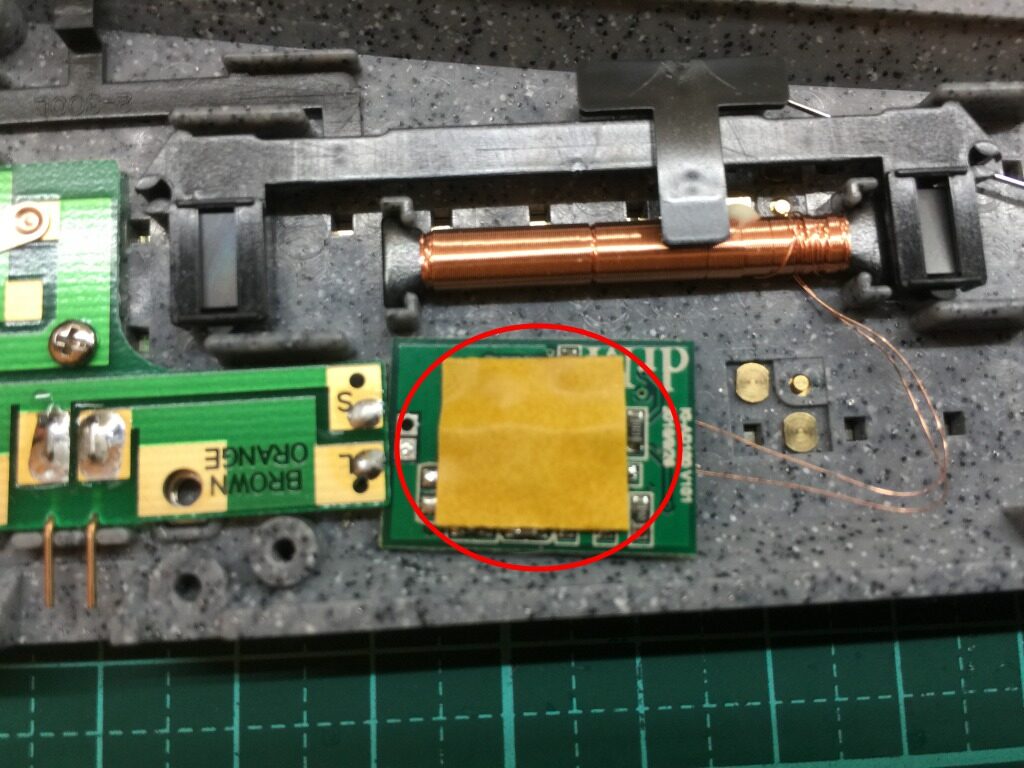
Double-sided tape can be used for fastening the DCC decoder on turnout.
Rework to connect DCC decoder with solenoid as the BLUE and RED indicated line in the figure.
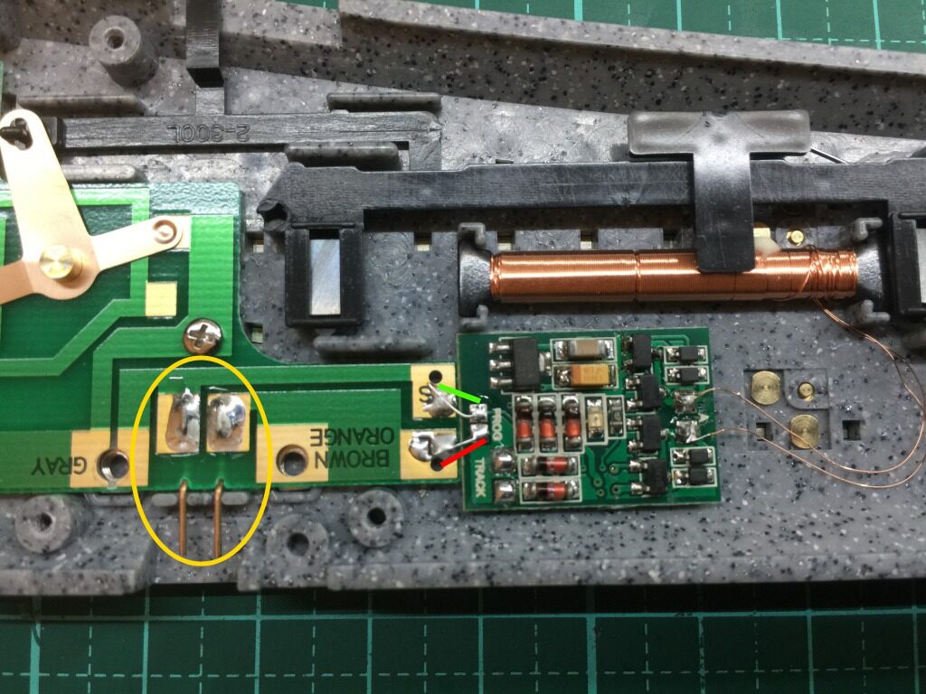
Connect DCC decoder with the PCB’s S point and L point (as the GREEN/RED indicated lines). In this connection, the JUMPER can be used as one of configurable setting for DCC decoder.
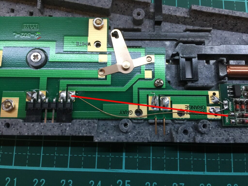
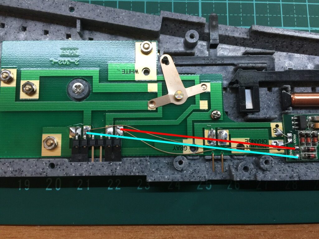
In order to supply the power of turnout from DCC decoder, shall follow the RED/CYAN indicated lines in the figure to rework.
Final, put the PCB back and install the screws to complete this installation.
Configure the address of DCC decoder demo video.
Install DCC decoder on Kato HO turnout demo video.